The ideal way to build a national broadband network for access to the Internet would be with a high-bandwidth, bidirectional cable running to each individual household. But sometimes you have to work with what you've got, and in America, what we have are cable TV networks. These networks have the bandwidth, but not the bi-directional part—they weren’t originally intended for two-way communication. Worse, the cables for many neighbors all connect together, so it's not possible to send a signal to just one household. And yet, cable companies manage to provide 100 Mbps bandwidth to their broadband customers using this flawed infrastructure, and they do it without compromising the preexisting cable TV service. The tech behind this magic trick goes by the name of DOCSIS, which stands for Data Over Cable Service Interface Specifications.
In this two-part series, we'll take a detailed look at DOCSIS—what it is and how it evolved. If you've ever wondered how cable TV companies manage to get progressively more bandwidth out of the same old cable lines, then this series is for you.
Of course the story doesn't start at 100 megabits per second. The earliest attempts to provide broadband service over the cable (take the word "broad" with a grain of salt here) was using one-way systems where the return path was over a phone line. One of the first true cable broadband systems was developed by LANcity. The LANcity cable modems treated the cable network as a very big 10 Mbps Ethernet segment.
Coaxial cable
Traditional 10 Mbps Ethernet also uses coaxial cable, just like cable TV (actually the cable has slightly different specifications). A coax cable consists of an inner wire wrapped within an insulator which is in turn surrounded by an outer conductor. So the inner wire is protected against electromagnetic interference from the outside, and the outer conductor is grounded so it's not susceptible to interference, either. This makes it possible to use the same TV channels for cable that are also used for broadcast over the air (within reason, because, in practice, the shielding isn't perfect).
The big difference between Ethernet over coax and data over the TV cable is that Ethernet puts voltages directly on the cable. The way in which the voltages transition makes up the 0 and 1 bits. This straightforward mode of operation is called "baseband" transmission—hence the name 10BASE2 (10 Mbps baseband transmission over (almost) 200 meters).
Baseband transmission is simple to implement, but has the downside that there can only be one signal at a time on the wire. So with multiple systems connected to the same wire, the systems have to take turns transmitting data by waiting until the wire is idle. When two Ethernet systems accidentally start to transmit at the same time, they each notice the other's transmission, declare a "collision," and retry a little later. The systems use a random wait time, so the retransmissions usually don’t collide again.
On a cable network, things are done somewhat differently. In order to coexist with the TV (and radio) broadcasts living on the same cable, the digital signals are modulated into 6 MHz channels (or 8 MHz in many places around the world), just like TV channels. In the downstream direction (from the cable operator to the user), the digital information is carried on an unused TV channel.
The tricky part is the upstream direction, from the user to the cable operator. Fortunately, in the past, cable networks have been outfitted with limited capacity in the upstream direction, sometimes called the "subband." This is the lowest part of the frequency band used for cable TV, and it was often used to carry programming from cable access stations to the cable operator's "head end," where all the equipment for injecting content into the cable network resides. Frequencies from 5 to 42 or 65 MHz are used for return traffic, while higher frequencies, up to as high as 1 GHz, are used for broadcast and downstream traffic.
A bandwidth timeshare
So now we have high-bandwidth and a bi-directional infrastructure. This leaves just one problem: the fact that multiple users are connected to the same cable. In the downstream direction, this isn't a huge problem. Just like on an Ethernet network, every data packet is addressed at the intended recipient, and everyone simply ignores packets not addressed to him or her.
In the upstream direction, however, things are more complex. What if multiple users send data at the same time? Although it's possible to adopt the classic Ethernet collision-and-retransmit mechanics to this problem, that's not very efficient as cable lengths increase—or at all, really. So instead, DOCSIS uses the TDMA (Time Division Multiple Access) technique that is also used in cellular telephony. With TDMA, the channel is sliced into small timeslots—called “minislots”—that are then doled out to the cable modems (CMs) by the cable operator's CMTS (Cable Modem Termination System). It typically takes multiple minislots to transmit a single IP packet. By giving a cable modem more or fewer timeslots, the CMTS can control exactly how much upload bandwidth each cable modem gets to use.
Timing and the speed of light
Because the minislots are so small—there are typically 40,000 minislots per second—the timing of the different transmissions is very critical. If a certain cable modem transmits too early, it's going to step on the previous timeslot, but if it transmits too late, it overlaps with the next one. So every cable modem must be properly synchronized with the CMTS to avoid problems.
The trouble is that different households are at different distances from the head end, and at 25 microseconds per timeslot, the speed of light can't be ignored—a few miles or kilometers difference in cable distance between two households will make one house trample all over the other's timeslot. So when a CM initially contacts the CMTS, the CMTS sends feedback about the time it takes for the CM's transmission to arrive, so the CM can compensate for this and stay within its assigned timeslots. When this procedure has been carried out successfully, the cable modem is synced to the CMTS and ready to exchange IP packets.
DOCSIS nuts and bolts
The original DOCSIS 1.0 specification was developed in 1997 by CableLabs and certified in 1999. DOCSIS 1.1 followed in 1999/2001, and 2.0 in 2001/2002. The benefit of DOCSIS 2 over 1 is in the upstream direction, which gets better performance in noisy environments as well as better bandwidth. In DOCSIS 1 the upstream channels can be between 200 and 3200 kHz wide, DOCSIS 2 also adds 6400 kHz.
| Upstream | Raw Bitrate | Downstream | Raw Bitrate | |
|---|---|---|---|---|
| DOCSIS 1.0 and 1.1 | 200 - 3200 kHz, QPSK or 16QAM | 0.4 - 13 Mbps | QAM64 or QAM256 | 36 or 43 Mbps |
| DOCSIS 2.0 | 200 - 6400 kHz, QPSK - 128QAM | 0.4 - 36 Mbps | QAM64 or QAM256 | 36 or 43 Mbps |
| DOCSIS 3.0 | n * 200 - 6400 kHz, QPSK - 128QAM | max n * 36 Mbps | n * QAM64 or QAM256 | 36 to 172 Mbps (with 4 channels) |
Upload speeds in DOCSIS 2 are also helped by new modulation techniques, which cram more bits in each "symbol." And there's a completely new way for multiple modems to share the upstream bandwidth: S-CDMA (Synchronous Code Division Multiple Access). S-CDMA allows multiple cable modems to transmit at the same time, and it’s also more resistant to the noise that is present on channels below 20MHz. Let's look at both the bits-per-symbol and S-CDMA issues in more detail.
QAM modulation
For those who aren't electrical engineers or didn't live through the dial-up era, I'll explain the issue of bits-per-symbol. With non-baseband transmission, the signal that we want to get across is modulated on a carrier. This way, every transmission can have its own frequency without getting in the way of anyone else. However, every time there is a change in the data signal, this distorts the purity of the carrier, making it spread out across the frequency band. The extent of this invasion into neighboring frequency space is determined by the frequencies in the signal that we modulate onto the carrier, which in turn depend on how often per second we change the data signal.
So the frequency band we are allowed to use puts a limit on how many times per second we can change the data signal. For this reason, it's not possible to have a baud (changes per second) rate much higher than 2400 for modems over the phone network, which provides a frequency band from 300 to 3400 Hz. However, all is not lost—there is no reason we can't have many more "symbols" than just 0 and 1. So rather than have our carrier encode 0s and 1s, we can have it encode a larger number of values. For instance, with dial-up, the V.32 standard uses a baud rate of 2400, but each of those 2400 changes per second can be between no less than sixteen distinct symbols. This lets the modem transmit four bits per symbol, for a total bitrate of 9600 bits per second.
Coincidentally, one of the modulations for the upstream direction in DOCSIS is the same as with our 9600 bps modem. But with 1600 kHz rather than 3.1 kHz to work with, DOCSIS 2.0 supports a symbol rate from 160 to 5120 kHz and 2 to 7 bits per symbol, using QPSK (Quadrature Phase Shift Keying, two bits per symbol) and 8QAM to 128QAM (3 to 7 bits per symbol).
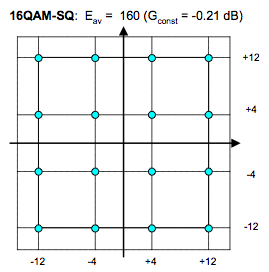
QAM is Quadrature Amplitude Modulation. This is a system where a symbol is encoded as a shift in both phase and amplitude of the carrier. For instance, 16QAM has four distinct phase shifts and four amplitude shifts. These are often drawn in a "constellation" that shows all possible combinations.
Electrical engineers casually talk about the real and the imaginary parts of a symbol, which allows them to use math based on the imaginary number i, which is the square root of -1, to unravel these complex encodings quickly and efficiently.
reader comments
114